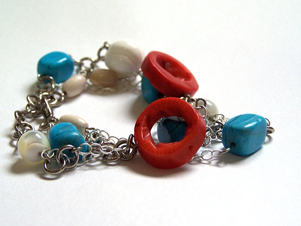
The Full Adder Circuit Bracelet, deconstructed*
The bracelet, as pictured here, has had the clasp taken off so I could present a more organized, easy-to-see reference image. On the clasp end, you have the inputs: A, B, and Cin. On the opposite end, you have Cout and S. They connect to the different gates and, unlike a circuit diagram, I've shown the values between gates. When B (value of zero/off, represented by the cream-colored mookaite tube) and Cin (value of one/on, represented by the faux turquoise) input to the first XOR gate, it outputs one. And when the second XOR gate has two "on" inputs, it outputs zero/off. (These are all obviously very amateur terms; like I said, I'm not a hardware freak or an electrical engineer.)
Of course, it's hard to represent something that's flat, brittle, and broad in a medium that's curved, fluid(ish) and narrow. This is a piece whose nerdiness must needs be subtle. I dig it, though! I think the overall effect is quite stylish.
*At the time of this photographing, there was a small error; a chain had broken off at work and I reconnected it at the wrong place. It's fixed now, and all loops in all chains have been secured. :)


No comments:
Post a Comment